Friday, March 24, 2023

Battery Drain Testing (2010 Toyota Camry)

 Word on the street is that I have a machine that will tell me what is draining a battery overnight. No. But I do having testing equipment, system data, experience and patience. I also have a typical procedure, but is adaptable to match testing results. 

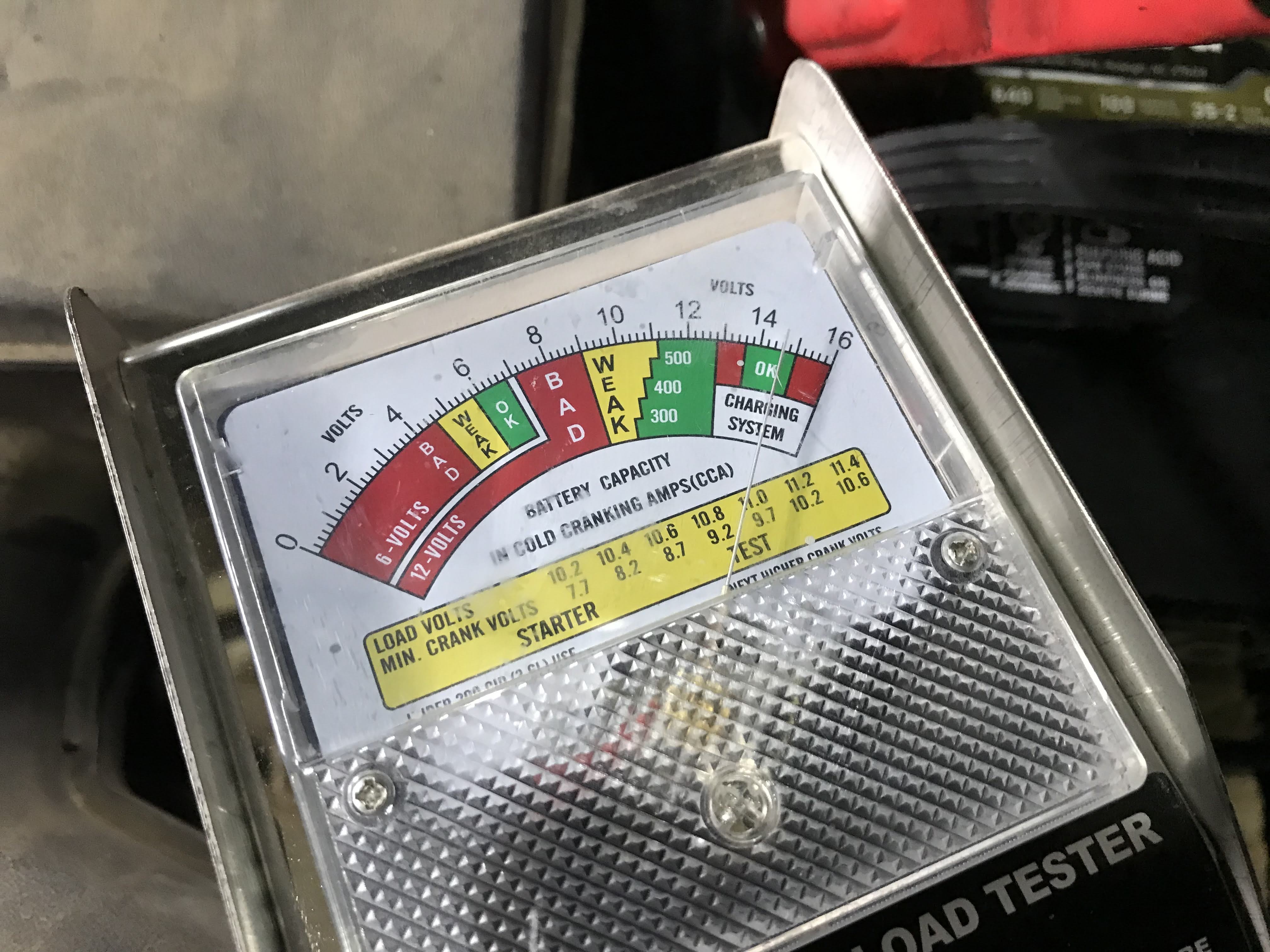
First is, make sure the battery is good and fully charged. This means test and charge as needed. No guessing, no judging based on anything other than testing. This particular battery was new but discharged. You'll need a good, dependable battery charger that reports battery charge condition as a percentage. With the battery still connected to the car, I put the charger on and saw 0%. When my charger sees very low battery condition it goes into "battery saver" mode. Basically that is a trickle charge until the battery begins accepting more charge. So I'm connected and charging in "battery saver" mode, battery is connected to the car. Three minutes later I am showing 99% percent charge, which is a sign of a bad battery or I do have a large drain on the battery and it is interfering with the charge. Disconnecting the battery cables and charging the battery independently gave me a 19% charged reading and more normal charging. I tried testing the battery and saw that I was not going to get by without a charge. 


A slow charge is a good charge so this was going to be an overnight charge. You always want to feel the sides of the battery case for any overheating or watch for any over venting, or acid boil. Internal battery faults can cause dangerous conditions and you don't want the car sitting on an overnight charge unless it is safe to do so. Next morning battery is charged and good. I make the first battery test with a load tester, then the digital tester. 


Reconnect the battery to the car, making sure the connections are good. 

Next step, check the alternator is working properly. At this point all we really have to know is that the alternator is charging the battery when the engine is running. Even though the complaint is a battery draining overnight, the alternator not working properly could cause the battery to be low when the car is shut off, and discharged next morning based on the fact the battery had low voltage when parked. We can do a simple voltage test at the battery and get enough information. Just put a dependable voltmeter on the battery and note the voltage, key off. Start the car and note the voltage with the engine running, if the voltage is more the alternator is charging the battery. That is all we have to know for the purpose of going further in battery drain testing. (Note: if you find your alternator is not working, it does not mean your alternator is bad. It means the charging system needs further testing.)


Prepare for draw and circuit checks. You'll need access to the battery cables themselves for an amp clamp. You'll need access to fuse blocks and relays. Usually there is a fuse block under the hood and one inside the car. You have to set things up for access prior to the testing because computers on a car take some time to go to "sleep", or stop drawing battery current. That time varies according to car, but the important part is that you have to wait for the "sleep" period to begin testing or you will show draw when it is normal and not a fault. 


If you open the door for access to the interior fuses while in sleep mode you will wake the system again. You have to fool the car into thinking the door is closed while it is actually open so that you have access without waking the car. The latch can be closed onto a screwdriver. This car also has a door jamb switch. I clamped the the switch in the depressed position, so as far as the car is concerned the doors are all closed. 


All set? I noticed the door ajar light was still on. The doors were shut, except the driver's but I had the latch and switch in closed position. Now at the beginning of this project, the customer had said the trunk would not close properly and his trunk light had been running the battery down but he had taken care of that. I had kept that in mind and was going to make trunk lamp related circuits a starting point once I was testing draw. But here was the light on that said a door was open and a trunk that didn't close properly so I went to the trunk to look at the latch. The striker is broken and the trunk was being held by  tarp strap. The most important thing though was that the latch was in the open position. I pushed it to closed with a screwdriver, same as I had done with driver's door, and the door ajar light went off.
 

Was that the problem? A door ajar light staying on? I can verify that. There are two ground cables off the battery and two positive cables. You can check current draw on either positive or negative but you have to check any cable that feeds off that side. The two positive seemed to have enough room for the clamp. I use a clamp because I can do that without disturbing the circuit. 


I'm looking for excessive current draw and there is none. I disconnected the sensor at the trunk latch and put the tarp strap back in place. There are limited places to attach a tarp strap on this trunk lid for sure. Now if we had to do this the more tedious way, as in a problem less easily noticed, we would have began pulling fuses, relays, power feeds, etc as we looked for the excessive draw to lead us to the fault. 

This one, not so difficult. 


Kenneth Hayes

Kenny@ggauto.repair

Thursday, March 9, 2023

Diagnostic Tech: 02 Buick Century A/C (originally posted August 2007)

 Thursday, August 23, 2007

Diagnostic Tech: 02 Buick Century A/C

It's been a hot summer and that places a lot of demand on air conditioning systems. Today's project is a 2002 Buick Century, automatic transmission and the 3.1 vin J engine. The complaint is no cold air from the air conditioner. On the drive into the service area I notice the blower works fine and the air flow is from the proper vents. When I cycle the A/C switch on I notice there is no compressor clutch engagement and there is no electric cooling fan operation.
Remember, when you turn the A/C switch on you are making a request to the powertrain control module. If the PCM sees the request and determines the conditions are correct it will engage the compressor clutch and it will engage the cooling fan. Since neither the fan or compressor are engaging I'm going to initially look for a condition that would cause the PCM to "decide" not to comply with the request. The system on this particular car is not automatic temperature control but a manual system with dual temperature control. The manual system looks at fewer inputs then the automatic so *should* be easier to diagnose.
One very basic check is system pressure. If the system pressure is too low, the PCM will not turn the A/C on. I choose to connect a set of gauges to the system for the pressure test. That way, if the system proves to be low of refrigerant I'm ready to charge it without missing a beat.


In this case the stabilized pressures are approximately 120psi so there is plenty of refrigerant and certainly enough to allow the compressor to engage. Since I have started along this path though it's a good idea to continue the journey before looking elsewhere. *I* know the system has good pressure but I don't know if the *PCM* knows it. The PCM won't be looking at a set of gauges, it will be looking at the pressure signal voltage from the pressure sensor. The pressure sensor is located in the pressure line in the area below the air cleaner housing.
I can check the voltage at the sensor with a meter but if I start with a scan tool and look at the A/C pressure sensor data I'll be looking at what the PCM "sees". If I start at the sensor and do the voltage check with a meter and the voltage checks good, I would still have to check the scan tool data. But, if I check the scan tool data first and it is good then there is no need to check the sensor voltage.

I can't miss an opportunity to check stored trouble codes so once I connect the scan tool I do just that. The PCM has stored DTC P0530. P0530 indicates a problem with the A/C refrigerant pressure sensor circuit. This code certainly tells me that I'm on the right path and I pull up the A/C pressure data items.


The A/C pressure readings are certainly out of the ordinary. The PCM sees no voltage from the pressure sensor and calculates a VACUUM condition (-15 psi)! I think it is time to do some voltage checks at the sensor. The pressure sensor has three wires. It has a 5 volt reference voltage, a ground and a signal return to the PCM. As the pressure changes the voltage on the signal return will vary. The PCM will use that voltage signal to determine system pressure.


With the sensor wiring connected I verify the reference voltage and ground are good at the sensor connector. A check of the signal wire shows no voltage so I'm almost ready to condemn the sensor. I need to verify the signal circuit is not shorted to ground. A short to ground would kill the sensor output voltage even with a good sensor. It won't work to disconnect the sensor and check for a ground on the circuit because the pulldown resistor inside the PCM would ground the open circuit. I wouldn't know if there was a short to ground unless I also disconnected the PCM connector. I didn't disconnect the PCM. I cut the signal wire a few inches from the sensor and checked for voltage on the sensor side of the wire. When I found no voltage output from the sensor then I KNEW I had a bad sensor.

FIX:

Replace the A/C Pressure Sensor.

Kenny@ggauto.repair

Thursday, February 2, 2023

Diagnostic Tech: '92 Astro Van, 4.3Z (originally posted March 2008)

 Saturday, March 01, 2008

Diagnostic Tech: '92 Astro Van, 4.3Z


I had a '92 Astro Van come in on the hook for a no-start. The engine was a 4.3 with throttle body fuel injection. The owner said the van had been stalling and sometimes failing to start for some time now. He had replaced the fuel pump and filter because he thought it seemed to be running out of fuel. No testing had been done and the same problem remained after the fuel pump replacement. When I turned the key on I could hear the fuel pump run. Turning the key to start engaged the starter, the engine spun nicely and... it even started right up! It isn't uncommon for a no-start to be towed in and then start once it gets here. I'm sure there is an applicable Murphy's law for that.

What I did notice though was an intermittent engine cut-out. A sure fire sign of a secondary ignition problem. Even though the van owner was still sure he had a fuel problem, I decided to take a look at the ignition system. On the Astro van the ignition system is easy to access once the engine cover is removed. I immediately saw what was probably causing that cut-out symptom I had noticed. There was a burn mark where the secondary spark from the coil wire had been jumping to a vacuum hose instead of following the intended path to the distributor cap. That meant that the resistance in the secondary, downstream of the coil wire was so great that the spark found it easier to jump to the vacuum hose. A mental list of plugs, wires, cap and rotor was forming in my mind.


As I began the work of replacing the secondary ignition parts I began to be amazed that this engine was running at all. The coil wire tower in the cap was completely burned away.


The rotor was burned through and the distributor was severely corroded.


After a cleaning with electrical contact cleaner and penetrating oil the distributor was found to be in good condition. I replaced the spark plugs, spark plug wires, distributor cap and rotor. The van ran very well after that with no more stalling or cutting out. At 264,000 miles I wouldn't be surprised if it did need that fuel pump as well.

Kenny@ggauto.repair

Friday, January 27, 2023

Cold Codes: P0406

I've been working with trouble codes and self-diagnostic systems since.. well, since they became part of car repair. The earliest systems were very different than OBDII. With OBDII there are more standardized aspects to testing. For instance, generic OBDII trouble codes all mean the same thing no matter the manufacturer. A P0406 breaks down to, P=Powertrain, 0=Generic, 4=Auxilary Emissions. The last two digits, 06 define the problem; EGR Position Sensor Circuit High. Notice that it does not say the problem is a bad EGR valve, a bad PCM, or anything about what is needed to repair the problem. The PCM uses a voltage signal output from the EGR position sensor to verify EGR valve operation. The code description is saying that there is a problem with the sensor voltage on that circuit. I will step back just a bit more, it is saying that there MAY be a problem with the sensor voltage on that circuit. Finding why the code set instead of what the code is, that is where actual diagnostics begin. The code P0406 means the same for each manufacturer but the system in place for EGR sensor monitoring would likely be different, which would make the testing different. The next step would be to verify the problem. 

A 2011 Jeep Wrangler, 4x4 3.8:


On the Jeep you would need to monitor the sensor signal looking for not only the correct voltage while commanding EGR but looking with a scope for a clean signal. From that point, you go where your testing takes you. I will say that on the Jeep it is indeed usually a bad EGR position sensor, which is part and parcel with the valve itself. 

On other makes the wiring would vary but you would still be looking for the EGR position signal and for a problem with that signal. 

2005 Impala:


On the Impala the sensor is usually fine but the EGR valve is sticking. Still, both parts are made together. Do the testing and know what you need. Always remember that a trouble code is there to steer you to the system where a problem may be. It isn't there to tell you what you need to fix the problem. 

Thanks

Kenny@ggauto.repair

Wednesday, January 4, 2023

Let's Talk Codes: '06 GMC Sierra P0030

 The very best way to find the problem causing a Malfunction Indicator Light (MIL) to be on is to understand the system, how it works and what it needs to be looking at to set a particular code. First, find what codes are stored. You are going to need to listen to the story of any work that was done, any parts replaced, sensors disconnected, batteries disconnected, etc. because those sorts of things could obscure codes, set codes unrelated to the problem and generally cause diagnosis to be more difficult. The best scenario is that no one has been trying to repair the problem and you are looking at relevant data. There are times when the data looks a bit suspect and you may need to clear the system and let it begin from scratch. From there, run the monitors and look for a MIL to come on again. Experience is your best tool to make that judgement. 

So, in this case we want to determine the cause of the MIL Check Engine light. I used a full function aftermarket scan tool because it will be tossing a wide net and querying other modules for codes as well as the engine module. There are times that diagnosis can be made more easily when several modules store codes that could be related. In this case I think I can concentrate on the powertrain codes. 


Generally when you have several trouble codes you start with the lowest numbered code. In this case, P0030. I would expect that P0053 is a very similar set of conditions and that the two are related to the same problem. Now in the conglomerate of minds that come together via the internet you may have been told that a trouble code tells you what your car needs. That isn't true. While trial and error guessing could be considered a diagnostic approach, it is a very poor one. Better is to understand what you are looking at and how to test the system. Both the P0030 and the P0053 indicate a problem with the heater circuit of the bank 1 sensor 1 heated oxygen sensor. This would be the upstream fuel control oxygen sensor on the driver side exhaust. The power feed comes from the O2a fuse and powers both B1S1 and B2S1 sensors. Each sensor is grounded through the ecm at a different terminal. Since we have no B2S1 code the fuse is good. The only power related problem would be wiring or connector to the B1S1 downstream of the fuse. We can check power and heater ground with a meter and a scan tool commanding the heater on. The codes indicate the heater resistance is out of spec at startup and on engine running. Two seconds at startup sets a P0053, and six seconds of out of spec running sets a P0030. The O2 heater can be commanded on with the scan tool and monitored with a meter. If the power is reaching the sensor, and if the ecm is capable of grounding the heater circuit to the sensor then the heater resistance should be within specs. If it isn't then the sensor is bad. If it is then verify the ecm is measuring the current correctly. 


In this case the B1S1 heater was bad. Replaced sensor. 

P0449 indicates the evap vent canister solenoid control circuit did not match the command. Battery + feeds the solenoid and the ecm expects to see that voltage on the command side when the solenoid is commanded off and ground on that side when the solenoid is commanded on. A scan tool can be used to make the commands and the circuit monitored with a meter to find the problem. 

In this case the vent solenoid was bad. Replaced vent solenoid.

Kenny@ggauto.repair


Tuesday, January 3, 2023

Diagnostic Tech: 1999 Ford Escort (originally published Aug 13, 2007)

 Today's project is a 1999 Ford Escort ZX2 with 2.0 vin 3 engine and with automatic transmission. The complaint is that the A/C is not cold. The blower works. The air flow is good and from the proper vents.

One of the other techs here in the shop has made some initial checks and informs me that there is sufficient refrigerant in the system but the compressor clutch does not engage. With that information I run a simple test on the drive into the shop. I make sure the A/C is turned off before I start the car and on the way into shop turn the A/C on. I'm listening for the radiator fan to run. It does run. The radiator fan is turned on when I turn the A/C on. Why is that important? I'll get to that.
On this car (and on most cars) you aren't actually turning the air conditioning on when you turn the switch on. You are sending a signal to one of the control modules "requesting" the A/C on. Under normal conditions the control module "sees" the request, checks that conditions are met to allow air conditioning to operate and THEN operates the air conditioning system. If the control module sees a condition that isn't within specifications, such as a low refrigerant condition, it won't command the air conditioning on.
The powertrain control module is the module used to control the compressor and fan systems on this car. When the PCM sees a request voltage at its connector pin 41 and it sees no reason not to run the air conditioning it should do two things that are important to this diagnosis. It should command the compressor clutch on and it *SHOULD COMMAND THE COOLING FAN ON*. The fact that the fan came on with the A/C switch turned on means that the control switch works and that the PCM sees no reason not to turn the compressor on. It even verifies the pressure switches are fine because the request voltage from the switch must pass through the low pressure switch and high pressure switch on the way to pin 41 of the PCM.
Since I know the problem is on the PCM output to compressor clutch side of the system the best place to do some tests is at the constant control relay module. The relay module is a true black box containing several relays and mounted directly under the air cleaner housing at the left inner fender. The PCM may be the one making commands but the constant control relay module is doing the work.


Pin 21 of the CCRM is the power feed to the clutch relay inside the module. It should be powered with the key on. This is easily checked with a circuit tester and there is power to the relay. When the relay is closed the power feed to pin 21 should be fed to pin 23 and on to the compressor clutch. When I apply power to pin 23 the clutch does work so I know the wiring to the compressor is good. Since I have power to the relay and know that the clutch will work with power then I know that the relay is not closing. To close the relay needs a ground signal at pin 22. This signal should come from the PCM. It is the "command" for the compressor clutch to operate.


The coil side of the relay is provided power by the PCM power relay. This means that with the engine running and the A/C switch off there should be voltage at pin 22 of the CCRM. With the A/C on and the PCM commanding the relay closed there should be a ground at pin 22. With the Power Probe circuit tester I find I have everything I need at the relay to make the relay close. The relay has failed. Since the relay is integral to the CCRM the entire module should be replaced.


Kenny@ggauto.repair


Thursday, December 29, 2022

Diagnostic Tech: 1992 Ford Tempo (originally posted Oct 11, 2007)

 Thursday, October 11, 2007

Diagnostic Tech: '92 Ford Tempo EECIV

We're going to need to set the Wayback Machine for 1992. Ford was using Electronic Engine Control System IV, or EECIV. By today's standards EECIV lacks sophistication but in its day it certainly performed its tasks very dependably.
On the plate today is a 1992 Ford Tempo w/2.3 engine and automatic transmission. The complaint is an intermittent Service Engine Soon light on and a high idle speed at that time. This system does store trouble codes in memory but should only turn the SES light while a code setting condition is present. In this case it just seemed to me that a test drive to verify the complaint was in order.
Initially the car ran fine. No light came on and even though I was driving in stop and go traffic there were no idle speed problems. I decided to return to the shop and just run the EECIV self-tests. When I pulled into the driveway the SES light came on. The idle speed was fine until I stopped and put the car's shifter into park position. The idle speed went to around 2000 rpm and stayed there for about three seconds before slowing back to normal. I had just verified the complaint. Time for the EECIV checks.
The car's test connector is at the left shock tower, near the battery. Technically there are two connectors. One is a single wire called the self-test input connector.
I'm going to mention that there are alternatives to retrieving codes. You don't have to use a scan tool. That being said, you will find the scan tool method more reliable with less chance of misreading a code number or accidentally clearing memory codes.
It is important to understand EECIV self-tests before using them to find a problem. Ford has the car's computer run specific tests and report back areas that failed the tests. The failures are reported as trouble codes. Running the tests improperly can give you misleading results.
A quick warmup cycle for the engine and I'll get started.
After connecting the scan tool to the test connector and entering the car data I want to start with "Quick Tests" and the Key On Engine Off tests. If a sensor fails the KOEO test then it should be repaired. You'll need a "Pass" or a no fault found condition in the KOEO self-test before any KOER (Key On Engine Running) tests can be reliably done.
The KOEO running test results are called "On Demand" codes. In this case I get a Pass code 111 which means no problems were found. After the On Demand codes are displayed the Keep Alive continuous memory codes will be displayed. The Keep Alive, or continuous codes are codes from the car's computer memory. Codes that have set in the past. This car has a 332 in memory. A 332 indicates insufficient EGR flow. I don't think a problem with the exhaust gas recirculation system it going to be related to the high idle or even the SES on at that time. An EGR not flowing should not cause the idle speed to be higher and since the EGR is not supposed to be flowing at idle anyway I don't think it would turn the light on at that time. I'm going to move on to the KOER tests because that test should be done before getting too involved with Continuous codes. The KOER test will reveal any sensor failures that happen during the test.
The KOER test codes indicate a 332 again. This time I know the EGR failed a test in real time and currently has a problem. Again though, I don't think it is related to the idle speed problem. Two more codes do indicate a problem with idle speed control, a 412 and 411. These codes indicate the car's computer not being able to control the idle speed. These codes do not store to memory so without running KOER tests we would not see them. If you think that was a lot of trouble to find that something is wrong with the idle speed you have a point. What was learned though is that the several sensors that contribute to the computer choosing an appropriate idle speed do pass self-tests. That means I should start by concentrating my efforts in testing the computer's ability to control the idle speed. In other words, I've learned that the inputs to the computer are likely to be fine but there is a problem with the idle control output circuit.
It's a good idea, I think, at this point to check the base idle and minimum air adjustment. Before any throttle adjustments are made I want to be sure I have a clean throttle plate. I'll remove the air intake hose, the MAF and the air cleaner cover as a unit. The throttle plate actually doesn't look too bad. It's pretty clean on the air cleaner side. The air filter looks good and the air cleaner housing was properly fastened.


When I open the throttle fully and look past the plate I can see major carbon buildup. I can even see why the EGR flow is low. The EGR passages are just behind the throttle body and fully plugged with carbon. The best thing to do here is remove the throttle body, remove the EGR valve and do some cleaning.


While we are in the neighborhood, this is a good time to remove the Idle Air Control (or Air Bypass Valve) and clean that passage as well. The engine computer uses this valve to control the amount of air that bypasses the throttle plate. The amount of air allowed controls the engine idle speed.

Once everything is clean and reinstalled it is a good idea to clean the MAF sensor or at least see if it needs cleaning. Two tamper proof screws hold the MAF to the MAF housing. A torx T20H will fit the screw heads. Carefully remove the MAF from the housing. With a magnifying glass and a good light you can look for dirt on the two tiny wires at the bottom of the sensor. If you see dirt, carefully clean it. These days there are spray MAF cleaners on the market. That wasn't always the case so I still use the same Berryman Spray Carb Cleaner that I always did. For stubborn spots I use a Q-tip as well.

This particular MAF looked pretty clean so after reinstalling it I let the engine warm up again. I know that I now have a clean throttle, a clean MAF, a clean IAC and a clean EGR passage but what I don't know is if I've fixed any of the complaints. It's time to run the KOER test again.

After getting the same results with the KOER self-test as before all this work, I decided to see just what was happening at the Idle Air Control as far as the computer control was concerned. The voltage at the IAC signal wire should roughly match the position being commanded by the computer. A command to open the valve 34% would have 3.4 volts. As a load is placed on the engine the command would increase, so a voltmeter could be used to check the command to see if the computer is trying to slow the idle speed during the high idle problem. Another method would be to disconnect the IAC wire connector from the valve and see if the engine slows. You see, the valve is spring loaded to return to minimum air position without a voltage command to the contrary. In fact, it is by disconnecting the IAC and adjusting the throttle position stop screw that minimum idle air is adjusted. All I have to do is wait for the high idle problem to appear. After a few minutes of running time the engine idle speed begins to race. When I disconnect the Idle Air Control the rpms do not change. The IAC valve is bad. I suspect a vacuum leak within the valve is the problem.

After replacing the IAC valve I now have no more racing idle and no more idle control related fault codes. One thing very good about the EECIV testing method is that I can rerun the test after a repair to verify the problem is fixed. The idle problem is fixed! BUT the EGR problem remains. I still have a 332 fault code in the KOER test.

During the KOER self-test the ECM will open the EGR vacuum regulator solenoid very briefly. This allows manifold vacuum to pass through the solenoid to the EGR valve. The vacuum should open the EGR valve. The pressure in the exhaust tube that runs to the EGR valve is measured by the PFE sensor. If the ECM has commanded the EGR solenoid to open yet does not see the PFE sensor voltage indicate a pressure change the ECM will assume the EGR is not working and will set the 332 fault code.


For testing purposes I like to use a length of vacuum hose and bypass the solenoid, feeding the vacuum directly to the EGR valve with the engine running at idle. If the engine nearly stalls then the valve is passing plenty of exhaust flow.

I started to do that here but noticed that the hose that feeds pressure from the EGR exhaust tube to the PFE sensor was broken. With a broken hose the PFE sensor would not be able to monitor the exhaust tube pressure change and would indeed set the 332 code. A replacement hose and another KOER test and this time the repairs were done! A complete system pass. No more light, no more high idle, no more codes!

Kenny@GGAuto.repair