Wednesday, July 16, 2008
Diagnostic Tech: '98 Buick Century 3.1
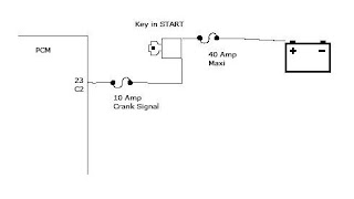
This starting system uses a crank relay. When the PCM sees the crank signal from the ignition switch on pin 23 of the C2 connector the PCM can close the crank relay by grounding pin 76 of the C2 connector. When closed, the crank relay allows the power from the 40 amp crank fuse in the underhood junction block to reach the transaxle range switch. When the range switch is in neutral or park position the power will pass through the switch to the S terminal of the starter solenoid.
This seemed like a good time to connect a scan tool to the car. With a scan tool I might see if there was a reason for the PCM to not engage the starter, such as a problem with the anti-theft system.
Well, there was a problem with communication. My scan tool would not communicate with the PCM. When I have that happen I try to make sure I've entered the vehicle information correctly. The information was correct so I tried to use the OBDII system to access the datastream instead of the GM system but still had no communication. It seemed like a good time to try a different scan tool. The second scan tool didn't help. I still had no communication. I checked for power and ground at the diagnostic connector. There should be battery power at pin 16 and ground at pin 4.
The power and ground were fine. A good class II data line communication can be easily seen with a graphing meter. The class II serial data is at pin 2. Sometimes there is a lot of communication, sometimes less. I had communication activity but I couldn't tell if any of that was from the PCM. There are several modules sharing the class II data bus.
What I could tell is that the bus was operating and there was communication on the line. What I wanted to know next is if I had a good bus at the PCM. The class II serial data line at the PCM is at pin 59 of the C1 (blue) connector. I used the graphing meter to check the data line at the PCM by backprobing pin 59 and I had a good bus. Next I cut the dark green wire feeding pin 59. That would mean that any activity I measured on the PCM side of the wire was coming from the PCM and any on the harness side was coming from another module. The harness side had a good signal. There was no signal from the PCM. I made a check of powers and grounds at the PCM connectors and pronounced this PCM dead.
I left the data wire cut and after connecting a new PCM I had a communication signal on the graphing meter coming from the PCM. I repaired the wire and reconnected the scan tool to look for communication. Success! I had a datastream on the scan tool. A peek at trouble codes gave me P1610 Loss of PZM/BCM Serial Data, P1626 Anti-theft System Fuel Enable Circuit and P1631 Theft System Password Incorrect. I guess the most worrisome part was the car still would not start. The starter would not engage. I suspected the P1610 was related to my having the open wire at the PCM connector and that the two Theft system codes could be handled with a password relearn. I cleared the codes from the PCM and used the following procedure to learn a new password.
Turn the key off, wait at least 30 seconds.
Turn the key to start, just as if you are starting the car, then release the key to run, just as if it had started.
The security light should either be flashing or on steady. Just let it do whichever it likes until it goes out completely. This can take as long as 30 minutes.
Once the security light goes out turn the key back to off and wait another 30 seconds.
Go back through the same procedure, turning the key to start, waiting for the light to go out again. You may have to repeat the entire process as much as a half-dozen times.
The first time you turn the key to crank and the car actually starts you are done.
On this car, the third time I hit crank it fired up. I had to go back into the PCM data to clear any codes that set during the procedure (P1630 and P1631) and then it was outta here!
Kenneth Hayes
AKA Deranger


No comments:
Post a Comment